This reference configuration shows how a conventional lead-acid sailboat house bank can be replaced with a LiFePO4 battery system for refrigeration, lighting, navigation equipment, pumps and inverter-powered onboard loads.
The system review covers battery sizing, inverter current, shore charging, solar integration, alternator charging, circuit protection and secure marine installation.
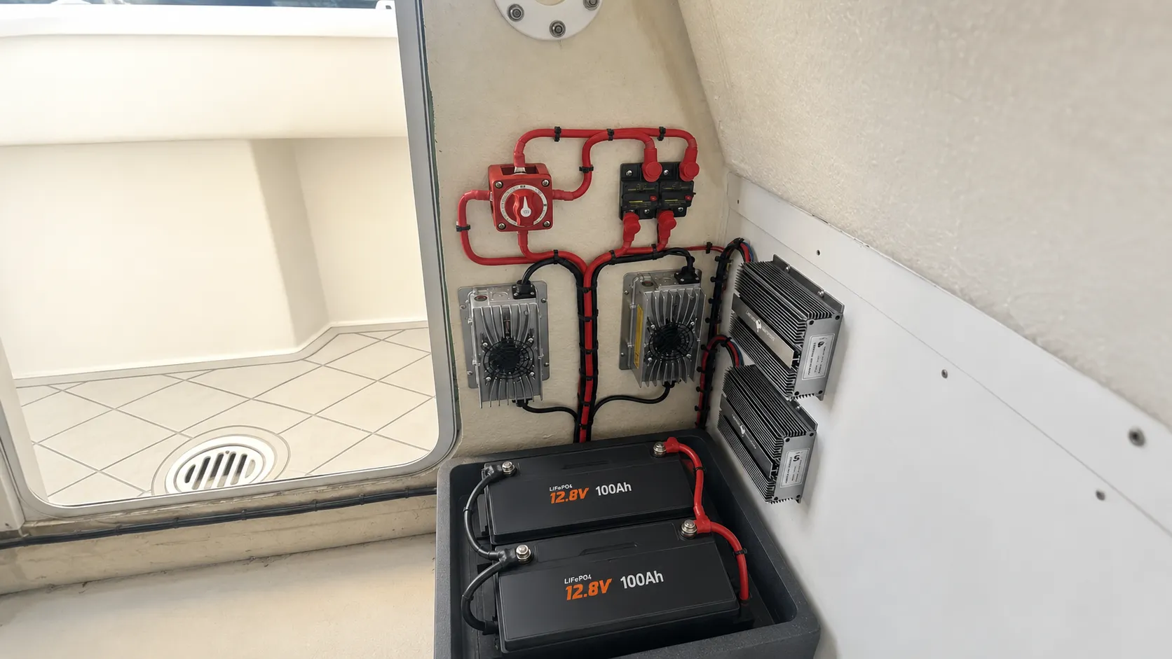
The replacement battery must provide more usable energy without requiring a complete rebuild of the sailboat’s 12V electrical system.
Typical project requirements include:
The following configuration is suitable as an engineering reference for a medium-size 12V sailboat house-power system. Final specifications must be confirmed against the vessel’s actual loads, original battery bank, compartment dimensions and charging equipment.
| Reference Original Lead-Acid Bank | 2 × 12V 100Ah AGM batteries connected in parallel |
|---|---|
| Reference Original Capacity | 12V 200Ah nominal |
| LiFePO4 Replacement | 1 × 12.8V 230Ah LiFePO4 battery |
| Nominal Battery Energy | 2944Wh |
| BMS Rating | 200A continuous discharge |
| Continuous Battery Output | 2560W at 12.8V |
| Reference Battery Dimensions | Approx. 19 × 6.7 × 9.5 in |
| Inverter | 12V 2000W pure sine wave inverter, 4000W surge |
| Calculated Inverter Current | Approximately 174A at 2000W and 90% inverter efficiency |
| Shore Charger | 14.6V 40A LiFePO4 charger |
| Solar Array | 400W reference solar input |
| Solar Charge Controller | 30A–40A MPPT controller with LiFePO4 settings |
| Alternator Charging | 12V 40A DC-DC charger |
| Monitoring | Optional Bluetooth monitoring, subject to the approved battery model |
This reference configuration is provided for system planning. Confirm the original battery specification, vessel loads, alternator capacity, cable lengths, fuse ratings and installation dimensions before production or installation.
In this reference configuration, two 12V 100Ah AGM batteries connected in parallel are replaced with one 12.8V 230Ah LiFePO4 battery.
Although both systems use a nominal 12V architecture, battery capacity alone does not determine compatibility. The engineering review must also cover:
A lead-acid house bank commonly operates with a restricted depth of discharge to protect battery life. A correctly configured LiFePO4 replacement can provide a larger share of its rated capacity while maintaining more stable voltage during discharge.
View Lead-Acid Replacement Batteries →
High-power inverters can draw substantial current from a 12V house battery. The battery, BMS, fuse, busbars, disconnect switch and cables must all support the expected load.
The approximate DC current can be calculated as follows:
Battery Current = Inverter Output ÷ Battery Voltage ÷ Inverter Efficiency
For the reference configuration, a 2000W inverter operating at 12.8V and 90% efficiency requires approximately 174A. This is within the 200A continuous BMS rating, but final cable and fuse selection must follow the inverter manual and applicable marine installation requirements.
The 4000W inverter rating is a short surge value rather than a continuous operating load. Equipment with high startup current must be checked against the battery’s permitted peak current and BMS protection settings.
The reference configuration uses a 14.6V 40A LiFePO4 charger connected to shore power. The charger must use a CC/CV profile suitable for the approved battery specification.
Dividing the rated 230Ah capacity by a 40A charger output gives a theoretical minimum of 5.75 hours. Actual charging time will be longer and depends on the starting state of charge, onboard loads, charging limits and current tapering. This value is a sizing calculation, not a measured project result.
Before retaining an existing shore charger, confirm:
Solar charging can support refrigeration, electronics and other onboard loads while the sailboat is away from shore power. Actual daily energy production depends on sunlight, panel orientation, shading, temperature and controller efficiency.
The reference configuration uses a 400W solar array with a 30A–40A MPPT charge controller configured for the LiFePO4 battery.
At 14.6V, a 400W solar array has a theoretical maximum charging current of approximately 27A before system losses:
400W ÷ 14.6V = approximately 27A
This is a sizing calculation rather than guaranteed solar output. The controller’s permitted input voltage and maximum solar power must also be checked against the panel arrangement.
The reference configuration uses a 12V 40A DC-DC charger between the engine alternator and the LiFePO4 house battery.
The DC-DC charger regulates voltage and current, provides an appropriate LiFePO4 charging profile and helps prevent uncontrolled current demand from the alternator.
Before selecting a DC-DC charger, confirm:
The engine alternator should not be connected directly to the LiFePO4 house battery unless the complete charging system is specifically designed and approved for that arrangement.
The house battery is integrated with the inverter, shore charger, solar controller, DC-DC charger and onboard DC distribution equipment.
Charging parameters, cable routes, fuse protection, busbars and isolation components must be checked before commissioning.
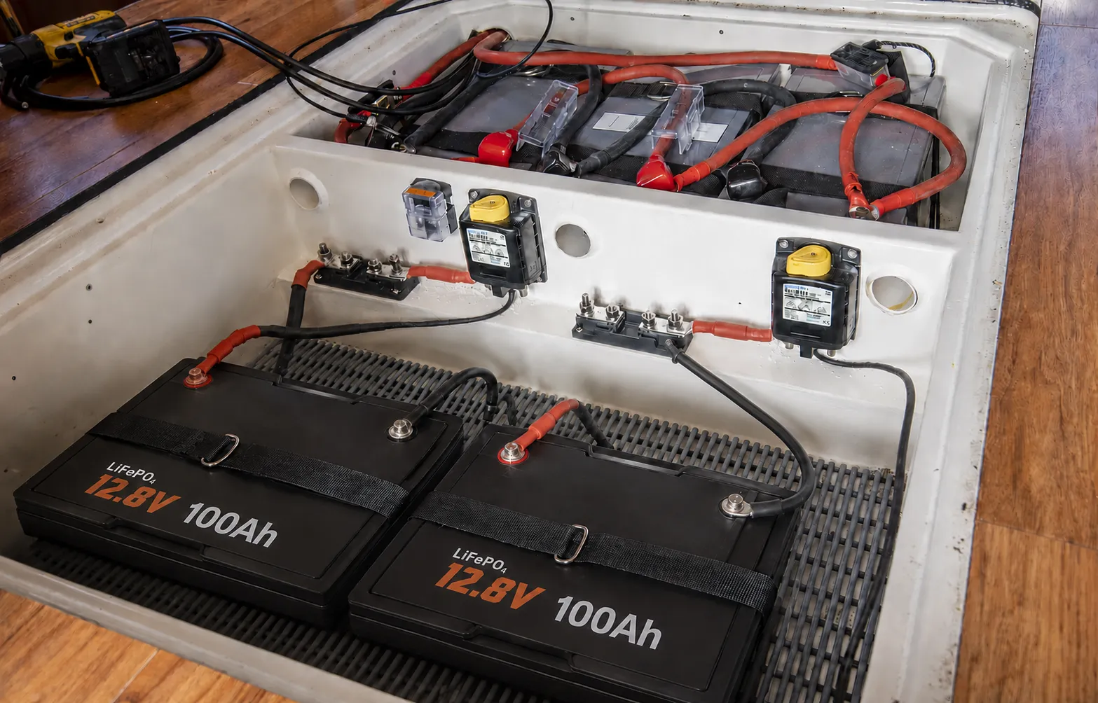
A sailboat LiFePO4 battery must be secured against vessel movement and installed with appropriate circuit protection, cable support and terminal protection.
The battery should be installed in a protected location away from standing water, excessive heat and direct mechanical damage. Environmental protection must be selected for the actual installation area.
The BMS must be selected according to the battery capacity, inverter current, charging equipment and operating conditions. The reference battery uses a 200A BMS to support the calculated inverter load.
Available functions can include:
Bluetooth, CAN, RS485, low-temperature protection and self-heating depend on the approved battery model and are not standard on every configuration.
After installation, the battery and connected equipment should be checked under charging and discharging conditions before the sailboat returns to service.
Measured commissioning results should be recorded for the completed vessel rather than inferred from component ratings.
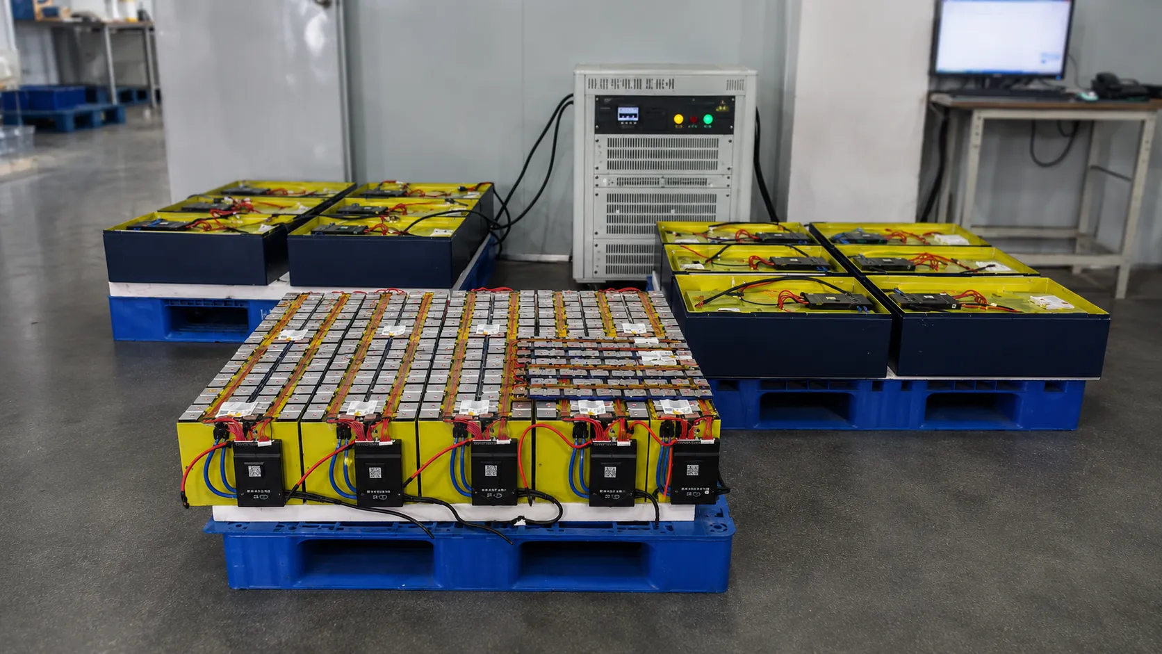
With more than 20 years of battery manufacturing experience, we support boat builders, marine equipment suppliers, system integrators and battery brands with custom marine LiFePO4 battery development.
OEM and private-label options include:
View OEM & ODM Battery Services →
Yes, when the replacement battery provides the correct system voltage, usable capacity, current rating and physical fit. The charger, alternator circuit, inverter, cables and fuses must also be compatible.
A 2000W inverter can draw approximately 174A when calculated at 12.8V and 90% efficiency. The battery must have sufficient continuous current capability. The reference configuration uses a 200A BMS, subject to final cable sizing, fuse selection and inverter surge requirements.
It may be retained when its voltage, current and charging profile are suitable for LiFePO4. A 14.6V 40A LiFePO4 charger is used in the reference configuration.
Solar capacity should be calculated from daily energy use, available mounting area, sunlight and required recharge time. A 400W array is used as an engineering reference on this page.
A DC-DC charger is commonly used when charging a LiFePO4 house battery from the engine alternator. Its output must be selected according to the alternator, battery and cable capacity.
Selected marine battery systems can support CAN or RS485. The required protocol and connected equipment must be confirmed before sample development.
Send us the original battery-bank configuration, system voltage, required capacity, inverter power, daily energy use, battery-compartment dimensions, shore charger, solar controller, alternator rating, communication requirements and estimated order quantity.
Our engineering team will review the electrical and mechanical requirements and recommend a suitable sailboat LiFePO4 house battery configuration.