Integrating a LiFePO4 battery into a Victron-based RV, motorhome or camper electrical system requires more than matching battery voltage and capacity. The battery, Smart BMS, inverter-charger, GX device, solar charge controller, DC-DC charger, DC distribution, cabling, protection devices and communication settings should be reviewed as one complete system.
This guide explains the main checks for integrating LiFePO4 batteries with equipment such as the Victron MultiPlus-II, Cerbo GX, GX Touch, SmartSolar MPPT, Orion XS and Lynx distribution components, with particular attention to CAN BMS communication, charging limits, system control and commissioning.
For broader charger, inverter and communication matching, see Lithium Battery System Compatibility. For RV battery selection and system planning, see RV LiFePO4 Battery Solutions.
Use the sections below to review the communication, charging, DC distribution and validation areas that matter most to a Victron-based lithium battery system.
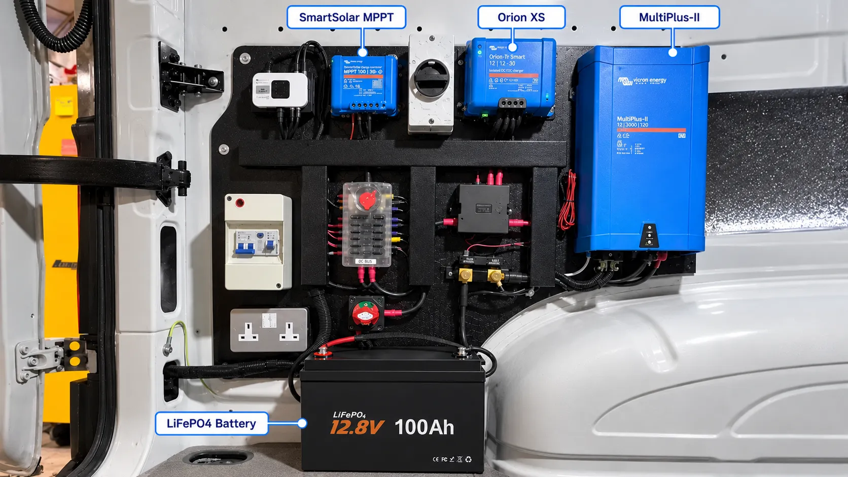
A Victron-based RV power system can contain several charging and control paths. The battery should therefore be treated as part of a coordinated electrical system rather than as a stand-alone component.
Depending on the RV design, common Victron components can include:
The exact equipment list varies by vehicle and system voltage. Confirm the battery specification, connected Victron models and complete electrical architecture before configuration.
CAN is the communication channel. The protocol is the language.
Two devices can both have CAN interfaces and still fail to communicate correctly. Before connecting a Smart BMS to a Cerbo GX or other GX device, confirm the communication requirements for the exact battery and equipment combination.
Review the following:
If a GX device reports no battery, CAN fault, communication lost or incomplete battery data, start with the protocol, port configuration, pinout, termination and firmware rather than replacing the battery immediately.
Seeing battery voltage or state of charge on a GX display does not by itself prove that the complete managed-battery integration is working correctly. Where closed-loop control is required, the system may also need to receive and correctly use battery operating limits and protection information.
Depending on the supported integration, relevant BMS information can include:
The required data set depends on the battery protocol and system design. Communication validation should therefore include both data visibility and actual charger/inverter response.
In Victron GX systems, DVCC can be part of the coordination between a compatible managed battery and connected charging equipment. It should not be enabled only because CAN communication is visible.
Confirm that DVCC is supported for the specific battery integration and that the required firmware, communication and system conditions are satisfied before enabling or commissioning it. If support is not confirmed for the battery configuration, treat the system as unverified rather than assuming closed-loop compatibility.
This is another reason battery compatibility should be evaluated at protocol and system-control level, not just by voltage, connector type or the presence of CAN.
The MultiPlus-II inverter-charger should be configured around the approved LiFePO4 battery charging limits and the complete RV electrical system. Nominal battery voltage alone is not enough to confirm charging compatibility.
Review:
If shore power is present but the battery is not charging, measure charger output and battery-terminal voltage before assuming the battery or inverter-charger is defective.
In an RV or camper, alternator charging should be reviewed separately from shore-power and solar charging. A DC-DC charger such as the Orion XS can be part of a controlled alternator-to-house-battery charging path when appropriate for the vehicle architecture.
Confirm:
Solar charging should also remain within the battery's approved voltage, current and temperature limits. When shore power, solar and alternator charging can operate at the same time, evaluate the combined charging current rather than checking each charger in isolation.
Review:
Multiple chargers can be individually suitable but still exceed the intended battery charging limit when operating together. Review the complete charging architecture during commissioning.
Communication compatibility does not replace correct high-current electrical design. Inverter and charging performance can still be limited by undersized cables, poor connections, unsuitable fuses or excessive voltage drop.
Check the complete DC path:
High-current faults often appear only under load. Measure voltage drop while the inverter or charger is operating instead of relying only on continuity checks.
Before approving an RV lithium battery system for repeated installation or OEM production, test the approved battery configuration with the actual or representative Victron equipment.
| Symptom | Check First | Possible Area |
|---|---|---|
| GX device does not detect the battery | CAN port, protocol and wiring | Profile/bit rate, pinout, termination, firmware or BMS configuration |
| Battery data is visible but charging is not correct | Charge limits and control behavior | Incomplete managed-battery integration, settings or charger configuration |
| SOC appears incorrect | BMS SOC data and synchronization | Monitor configuration, BMS data or incomplete full-charge synchronization |
| Battery charges on shore power but not while driving | DC-DC charger input/output | Alternator signal, wiring, fuse, configuration or battery protection |
| MultiPlus-II reports low battery under heavy load | Voltage at battery and inverter terminals | Cable voltage drop, BMS current limit, connection resistance or low SOC |
| Battery refuses charging in cold conditions | Battery and cell temperature | Low-temperature BMS charge protection |
For symptom-based diagnosis, use the RV Lithium Battery Troubleshooting Guide →
For RV manufacturers, camper builders, vehicle converters, distributors and system integrators, a battery configuration can be reviewed around the target Victron-based electrical system before sample development.
Project information should include:
Available communication functions depend on the selected battery model, BMS platform and confirmed project specification. Sample validation should be completed before repeated installation or volume production.
No. A CAN interface only provides the communication channel. The battery and Victron equipment must also use a compatible protocol, CAN profile or bit rate, pinout, termination and system configuration.
It can when the battery, BMS communication protocol and GX configuration support the required integration. Seeing SOC should still be followed by validation of voltage, current, alarms and any required charge or discharge limits.
No. DVCC support should be confirmed for the specific managed-battery integration and required firmware before it is enabled. CAN data being visible does not by itself confirm DVCC compatibility.
The charger settings and system configuration must be matched to the approved battery voltage, charging voltage, maximum charging current, BMS limits and temperature requirements. Compatibility should be confirmed for the exact battery configuration.
It can be part of a suitable DC-DC charging architecture when the vehicle voltage, alternator capacity, charger configuration, cabling, fuses and battery charge-current limits are correctly matched.
Data visibility does not necessarily confirm complete system control. Check the supported BMS data, charge limits, DVCC requirements where applicable, charger configuration and the actual battery response during charging.
For qualified OEM and integration projects, the battery voltage, capacity, current capability, Smart BMS, enclosure, connectors and supported communication can be reviewed around the approved system requirements. Compatibility and communication functions depend on the exact battery configuration and connected equipment.
Send the application, battery voltage and capacity, MultiPlus-II model, GX device, SmartSolar MPPT, Orion XS or other DC-DC charger, required CAN protocol, inverter load, battery-compartment dimensions and estimated order quantity.
Our engineering team can review the battery specification, Smart BMS communication, charging limits, installation requirements and applicable sample-validation scope for the project.
Victron, MultiPlus-II, Cerbo GX, GX Touch, SmartSolar, Orion and Lynx product names are referenced for system-integration context. Compatibility must be confirmed for the exact battery and equipment configuration.
