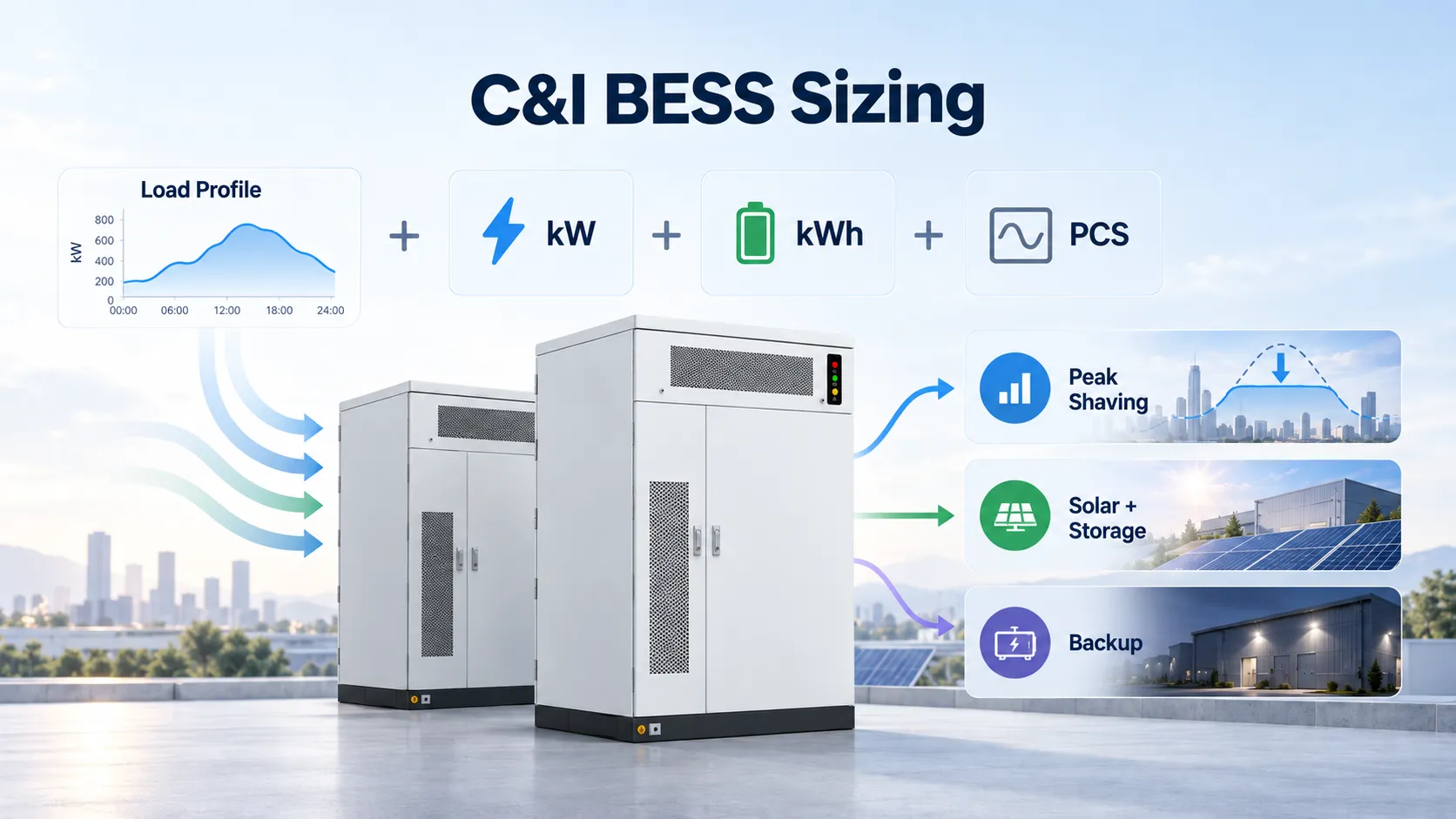
Size a commercial and industrial BESS by separating power in kW from energy in kWh, then matching PCS capability, battery capacity, operating duration and electrical integration to the actual site requirement.
The correct system size depends on the load profile and operating objective — not on battery capacity alone. Peak shaving, solar storage, backup power, EV charging and microgrid applications can require very different power-to-energy ratios.
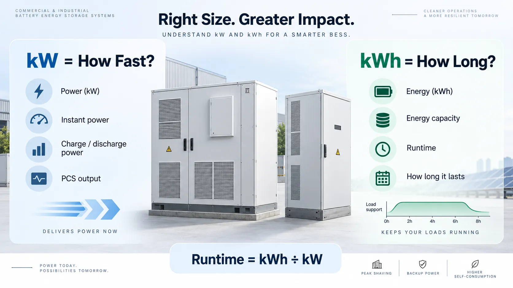
The first step in BESS sizing is to separate power from energy. A battery may contain enough energy but still be unable to deliver the required instantaneous power. Likewise, a PCS may have enough output power while the battery does not contain enough usable energy to sustain that output for the required duration.
kW defines how much active power the BESS must deliver or absorb at a given moment. It is a major driver of PCS power rating and battery discharge capability.
kWh defines the stored energy available to support the required power over time. It is primarily driven by the required load and operating duration.
The following equations are useful for preliminary system sizing. Detailed engineering should also account for manufacturer operating limits, system topology, environmental conditions and project requirements.
For peak shaving, this difference provides the preliminary AC power that the BESS may need to supply during the peak period.
This calculates the basic energy that must be delivered during the required operating period.
Additional allowance may then be required for reserve SOC, auxiliary consumption, temperature effects, degradation and end-of-life capacity requirements.
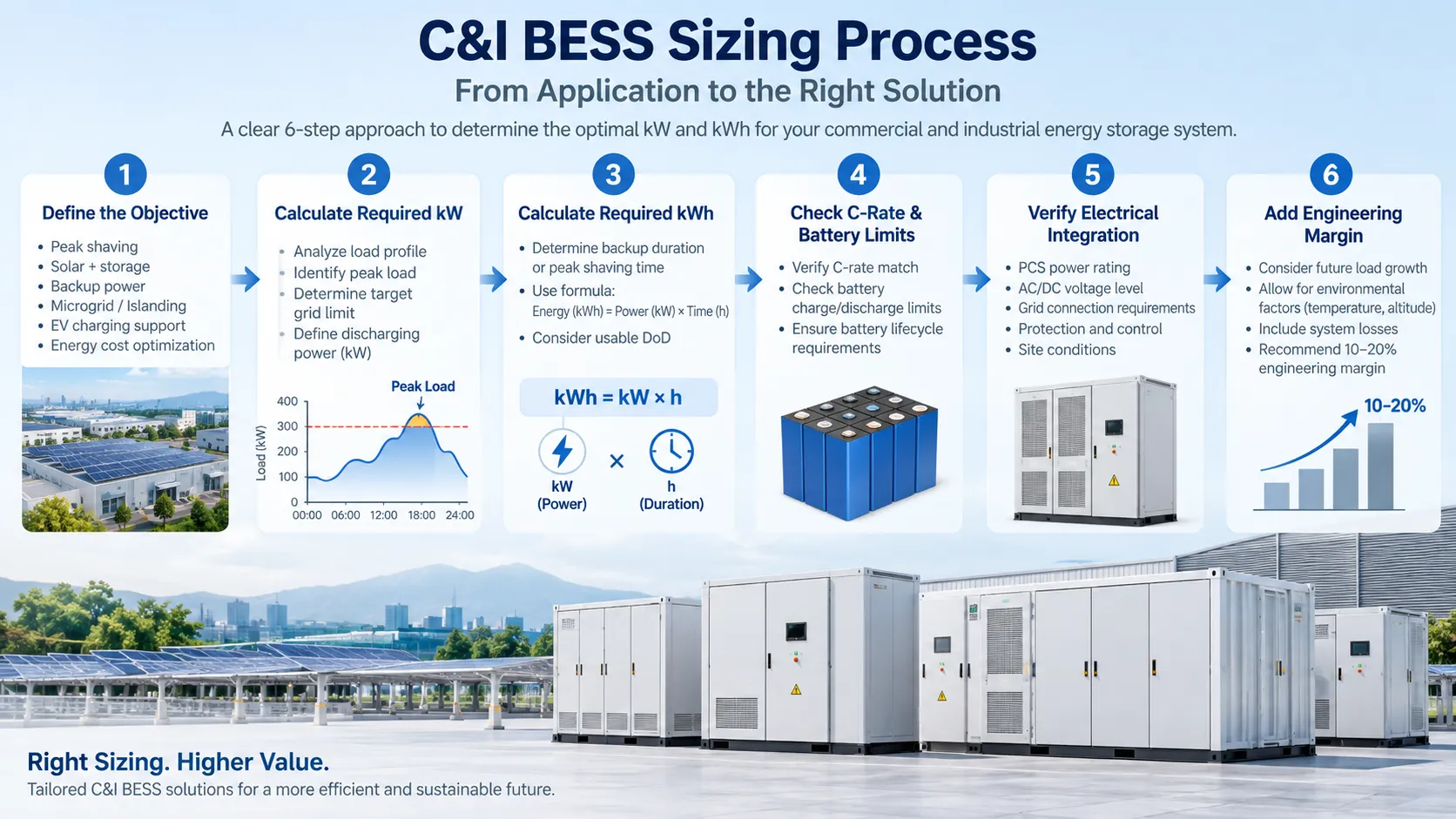
Reliable BESS sizing should start with actual electrical and operating data. Selecting a battery capacity before understanding the site load profile can lead to an undersized or unnecessarily oversized system.
Determine whether the primary objective is peak shaving, solar energy shifting, backup power, EV charging, tariff optimization or microgrid operation.
Identify maximum demand, peak duration, daily operating pattern, seasonal variation and recurring high-load periods.
Determine the maximum charge and discharge power the PCS and battery system must support.
Multiply required power by duration, then account for usable DoD, conversion losses, reserve energy and operating limits.
Check C-rate, battery current, DC voltage window, PCS power, overload capability and charge/discharge restrictions.
Check voltage, transformer, switchgear, protection, metering, EMS communications and grid-connection requirements.
Consider reserve SOC, battery degradation, end-of-life capacity, ambient conditions, cycle profile and expected future load growth.
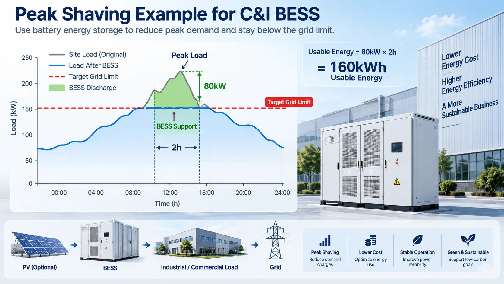
Assume a factory needs to reduce grid demand by approximately 80kW during a production peak that lasts about 2 hours.
The 160kWh value represents the basic energy required for the load-support period. It should not automatically be treated as the final installed battery capacity.
The final nominal battery capacity should also account for usable depth of discharge, PCS and discharge-path losses, reserve SOC, auxiliary consumption, temperature, degradation and required end-of-life performance.
The same battery capacity can behave very differently depending on how the system is used. The primary kW and kWh drivers should therefore be defined before selecting equipment.
| Application | Primary kW Driver | Primary kWh Driver |
|---|---|---|
| Peak Shaving | Difference between site peak demand and target grid limit | Duration and frequency of the demand peak |
| Solar + Storage | Required charging and discharging power | Surplus PV energy available for time shifting |
| Backup Power | Maximum critical-load power and transient requirements | Required backup runtime and reserve SOC |
| EV Charging | Charger concurrency, grid limit and charging peak | Duration and frequency of the charging shortfall |
| Microgrid | Critical or total site load and PCS operating strategy | Required islanded operating duration and generation profile |
C-rate describes the relationship between battery power and battery energy. As a simplified example, a 200kWh battery delivering approximately 100kW at battery level is operating near 0.5C.
When only AC-side PCS power is known, conversion efficiency should be considered before using the value as battery-side DC power.
The selected cell, module, battery rack, BMS, busbar and thermal-management system must all support the required charge and discharge current within their specified limits.
Battery energy is only one part of system sizing. Before selecting a final C&I BESS configuration, the complete AC and DC architecture should also be reviewed.
| Engineering Check | What to Verify |
|---|---|
| PCS Power | Required charge/discharge kW, overload capability and operating mode. |
| kW vs kVA | Check active power, apparent power and required power-factor operating range. |
| Battery DC Voltage | Confirm the battery voltage window is compatible with the PCS DC input range. |
| Transformer | Check site voltage, transformer loading, connection point and required step-up or isolation architecture. |
| Switchgear & Protection | Review breakers, protection coordination, isolation and connection requirements. |
| EMS & Metering | Confirm meter location, control logic, BMS/PCS communication and required protocols. |
| Backup Architecture | If backup is required, confirm PCS capability, switching architecture, critical-load separation and transfer requirements. |
| Thermal & Environmental | Check ambient temperature, altitude, cooling, enclosure rating, clearances and site conditions. |
Preliminary sizing should first establish the required power and energy. A specific BESS platform can then be evaluated against voltage, PCS capability, battery operating limits, thermal design and site integration requirements.
A 125kW commercial and industrial platform for projects requiring approximately 233kWh of rated battery energy.
View System Specifications →A higher-energy 125kW platform for C&I energy-management and scalable multi-cabinet projects.
View System Specifications →After preliminary sizing, review the applicable BESS datasheets, system architecture, single-line diagrams, installation documents and EMS/BMS/PCS integration information before final equipment selection.
Start with the required power in kW multiplied by the required operating duration in hours. Then account for usable depth of discharge, discharge-path efficiency, reserve SOC, degradation and other project-specific margins when determining nominal battery capacity.
kW represents the power the system must supply or absorb at a particular moment, while kWh represents the amount of energy available to sustain that power over time.
Determine the difference between the site's peak demand and the desired grid-import limit, then determine how long that reduction must be maintained. Both the required PCS power and battery energy should be checked against the actual load curve.
A battery can contain sufficient energy but still be unable to deliver the required power if the required charge or discharge rate exceeds the limits of the cells, modules, BMS or thermal-management system.
Determine the maximum critical-load power and required backup duration, then account for usable DoD, conversion efficiency, reserve SOC and operating limits. The electrical architecture must also support the required backup and transfer mode.
Yes. Expected capacity loss, cycle profile, operating temperature and the required end-of-life usable capacity should be considered during detailed system engineering.
Send us your load profile, peak demand, target grid limit, grid voltage, transformer data, solar PV capacity, tariff information and backup requirements. We can evaluate the appropriate BESS power, energy and system configuration for your project.
Request a BESS Sizing Review