Understand how BMS, PCS and EMS work together inside a Battery Energy Storage System to manage battery safety, bidirectional power conversion, energy scheduling, grid interaction and site-level control.
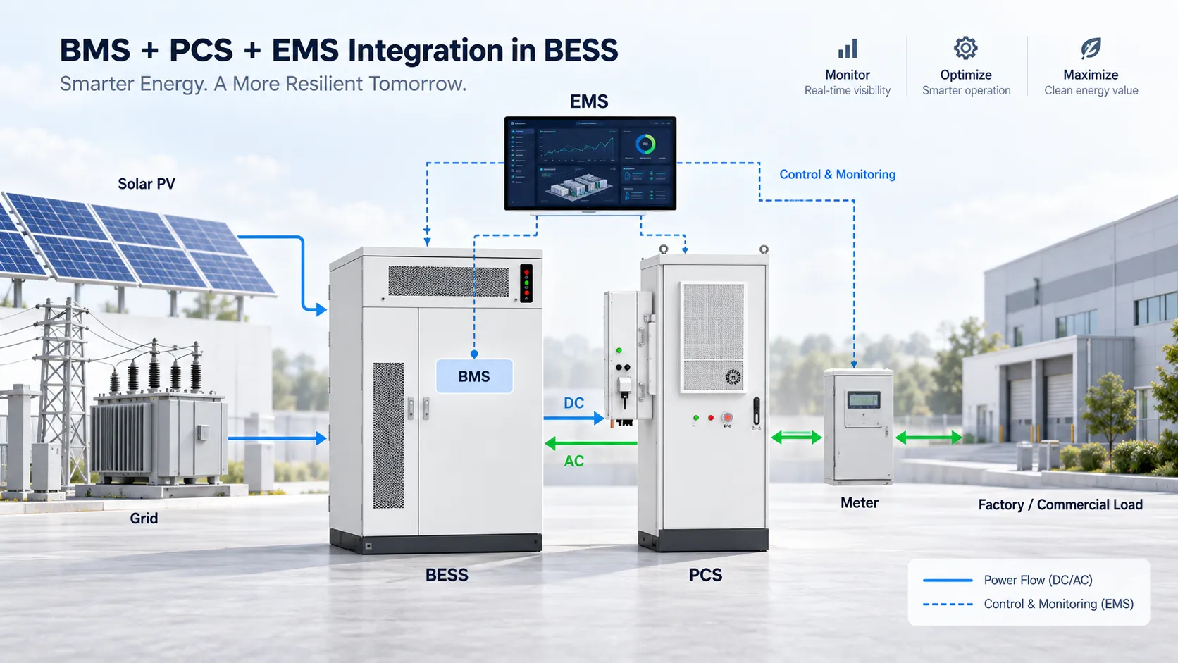
A BESS is not only a battery cabinet. Safe and effective operation depends on continuous coordination between the battery management system, the power conversion system and the energy management system.
The BMS protects and reports battery conditions, the PCS converts power between DC and AC, and the EMS decides when and how the system should charge or discharge according to site demand, tariffs, solar generation, grid limits and project objectives.
Monitors battery voltage, current, temperature, state of charge and protection status while enforcing battery operating limits.
Converts power between the battery DC side and the site or grid AC side and executes charge or discharge power commands.
Coordinates the BESS with site loads, solar PV, utility grid, generators and tariff or operational targets.
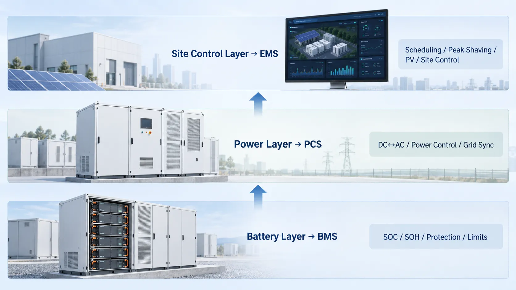
In a typical C&I BESS, the BMS provides real-time battery limits and status, the PCS executes power commands within those limits, and the EMS coordinates the complete site according to the operating strategy.
| Source | Typical Information | Used By |
|---|---|---|
| BMS | SOC, SOH, voltage, current, temperature, alarms, charge/discharge limits | PCS, EMS, local HMI |
| PCS | AC/DC power, operating mode, inverter status, grid voltage/frequency, faults | EMS, SCADA, local controller |
| Site Meter | Grid import/export, facility demand, real-time power flow | EMS |
| EMS | Charge/discharge power setpoint, schedule, SOC target, operating mode | PCS, site controller |
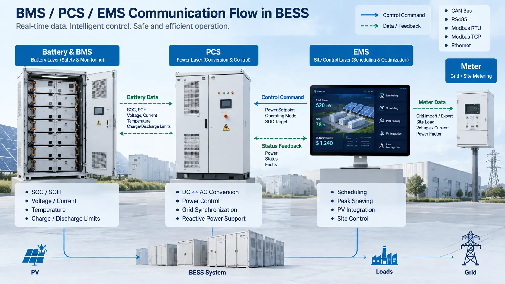
Communication architecture varies by battery, PCS, EMS and project design. Common industrial interfaces and protocols include:
The exact protocol map, register list and command priorities should be confirmed during engineering because compatibility depends on the specific BMS, PCS and EMS models used in the project.
Battery voltage, temperature, insulation and protection status are checked before normal operation.
The PCS initializes, synchronizes with the AC side where required and prepares for charge or discharge operation.
The EMS monitors grid power, load, PV output, tariff period and battery SOC.
The requested charging or discharging power is sent to the PCS within the available battery limits.
The PCS converts power while continuously monitoring AC and DC operating conditions.
If battery limits are approached, the BMS can reduce allowable current or trigger protective action according to the system design.
Assume a site wants to keep grid import below 500kW. If the site load rises to 620kW, the EMS can request approximately 120kW of BESS discharge, provided the battery and PCS operating limits allow it.
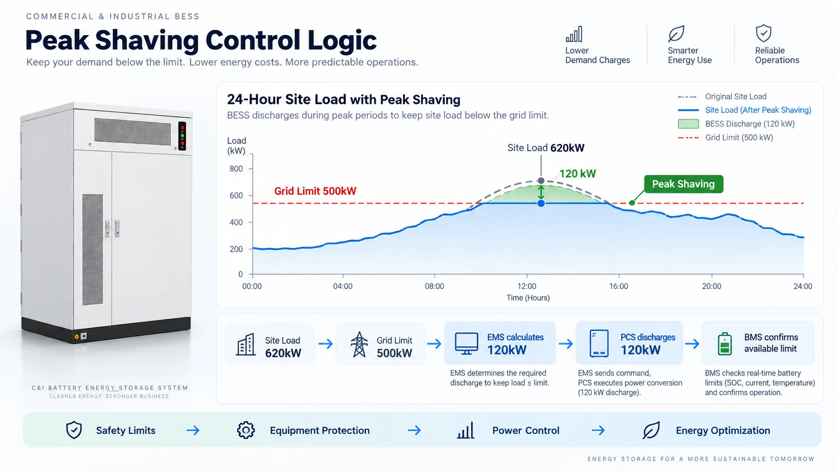
The final command must remain within the real-time BMS charge/discharge power limit, PCS rating, SOC reserve and site protection strategy.
The EMS may request charge or discharge power, but the BMS and PCS must enforce their own safety and operating limits. If battery voltage, temperature, current or system protection thresholds are exceeded, power should be limited or stopped according to the configured control hierarchy.
| Application | EMS Focus | Key Integration Point |
|---|---|---|
| Peak Shaving | Maintain grid import below a target threshold | Fast site meter feedback + PCS setpoint control |
| Solar + Storage | Maximize solar self-consumption | PV measurement + SOC scheduling |
| Backup Power | Maintain reserve SOC and critical-load availability | Switching, protection and backup-mode coordination |
| EV Charging | Manage charger demand and grid capacity | Real-time charger load + grid limit control |
| Microgrid | Coordinate grid, PV, generator, BESS and critical loads | Multi-source dispatch and islanding logic |
The BMS manages battery safety and operating limits, the PCS converts power between DC and AC, and the EMS coordinates when and how the BESS operates at the site level.
Normally no. The EMS typically sends operating commands or power setpoints to higher-level equipment such as the PCS, while the BMS independently enforces battery limits and protection.
CAN, RS485, Modbus RTU, Modbus TCP and Ethernet-based communication are common, but the exact protocol depends on the battery, PCS, EMS and project requirements.
Not automatically. DC voltage range, current limits, communication protocol, register mapping, startup sequence and protection logic must all be compatible.
Typical inputs include battery voltage range, charge/discharge limits, PCS ratings, communication documents, site voltage, meter configuration, EMS strategy, protection requirements and operating modes.
Send us your battery voltage range, PCS model, communication protocol, site voltage, operating mode and EMS requirements to evaluate the integration architecture for your BESS project.
Request BESS Integration SupportSend your site load, target capacity and application. Our engineers will reply with a matched BESS proposal and quotation.
