Selecting an AGV LiFePO4 battery requires more than matching nominal voltage and capacity. An AGV or AMR lithium battery should be reviewed against operating hours, route and duty cycle, average and continuous current, startup and peak current, charging intervals, communication requirements, installation space, and the operating environment.
For equipment manufacturers and system integrators, the objective is an AGV battery system that fits the vehicle, controller, charging station, and automation workflow. The final specification must be based on measured equipment data rather than a generic industrial battery assumption.
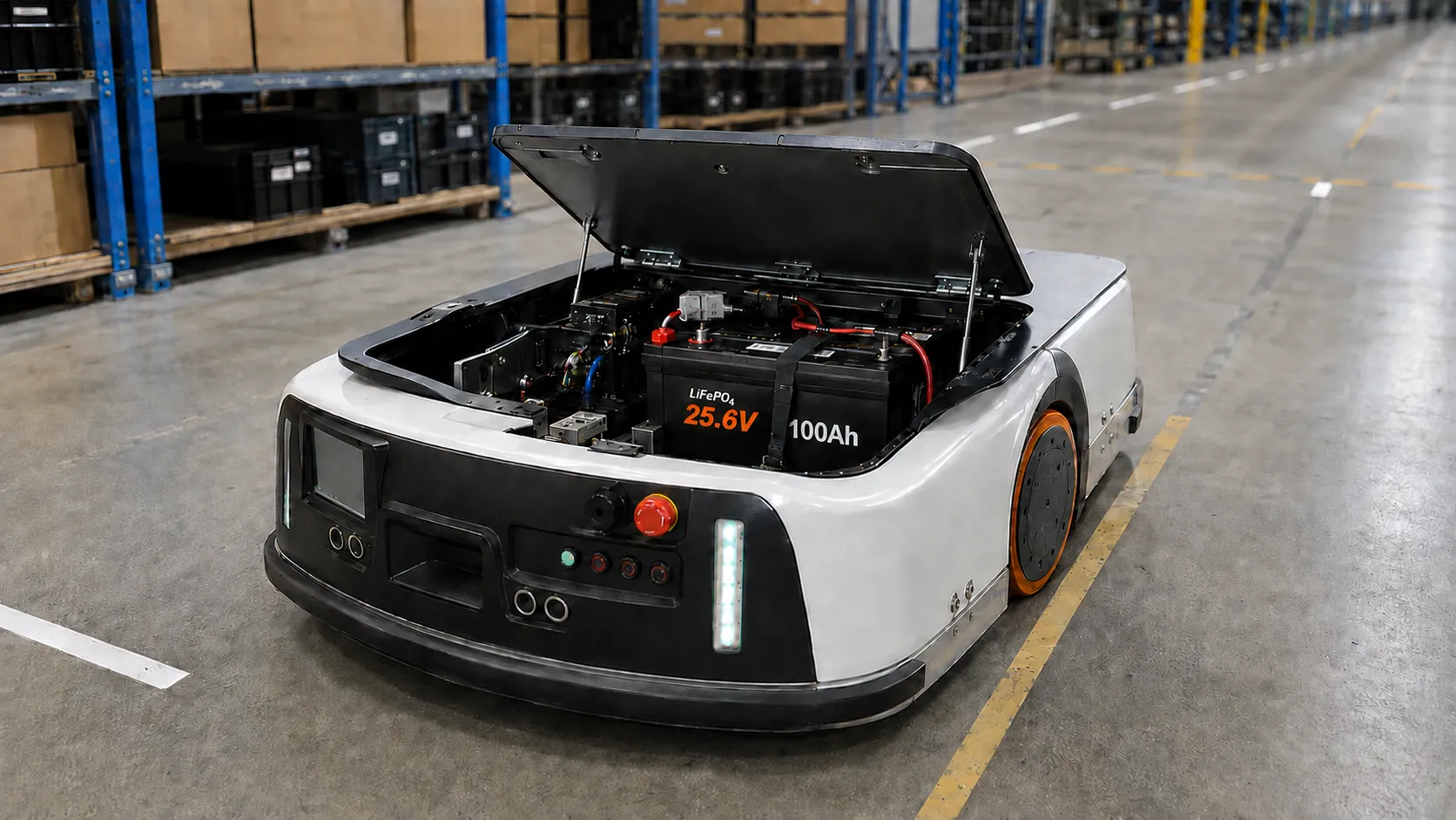
AGV and AMR battery selection should be based on the actual duty cycle and electrical load rather than voltage and capacity alone. Route length, acceleration frequency, lifting cycles, idle time, auxiliary electronics, and scheduled charging all affect the required capacity and current capability.
The specifications below are provided as a reference battery configuration for engineering review. They do not represent a completed or validated AGV installation.
| Nominal Voltage | 51.2V |
|---|---|
| Rated Capacity | 100Ah |
| Nominal Energy | 5,120Wh |
| Continuous Charge / Discharge | Up to 100A |
| Temporary Discharge | Up to 200A for 2 minutes |
| Peak Discharge | Up to 600A for 1 second |
| Enclosure | SPCC steel |
| Dimensions | Approximately 19.88 × 12.32 × 9.25 in |
Actual AGV or AMR integration requires confirmation of the equipment load, controller, charger, connectors, cables, installation space, BMS settings, and communication protocol. The reference values should not be treated as compatibility approval for a particular vehicle.
AGV runtime is driven mainly by average current across a representative duty cycle. A useful planning method is:
Calculated Runtime = Planning Battery Capacity ÷ Average Operating Current
Using 80Ah as a planning capacity, the following values are example average-current scenarios, not measured vehicle runtime:
| Average Current | Calculated Planning Estimate |
|---|---|
| 15A | Approximately 5.3 hours |
| 20A | Approximately 4.0 hours |
| 25A | Approximately 3.2 hours |
| 40A | Approximately 2.0 hours |
Actual AGV or AMR runtime depends on average load, acceleration frequency, route gradient, lifting and auxiliary loads, usable battery capacity, temperature, reserve requirements, and charging strategy.
An AGV lithium battery must support the normal continuous load and the short-duration current required for acceleration, motor startup, lifting, or conveyor operation. Record both the current and its duration. Controller phase current is not the same as battery current, so battery-side measurements or controller data should be used for specification review.
The reference battery limits above still require validation against the AGV controller, motor demand, cables, connectors, fuse or circuit breaker, and expected duty cycle.
Charging voltage and charging current must be confirmed for the selected battery configuration and charging station. Review the charging profile, contact polarity, connector rating, docking alignment, interlocks, emergency-stop logic, and any controller or charger communication before integration.
Opportunity charging may reduce long charging interruptions, but a higher charging current must be reviewed against cell and BMS limits, connectors, cables, thermal conditions, and charging-station capability. No specific opportunity-charging current is approved by this reference configuration.
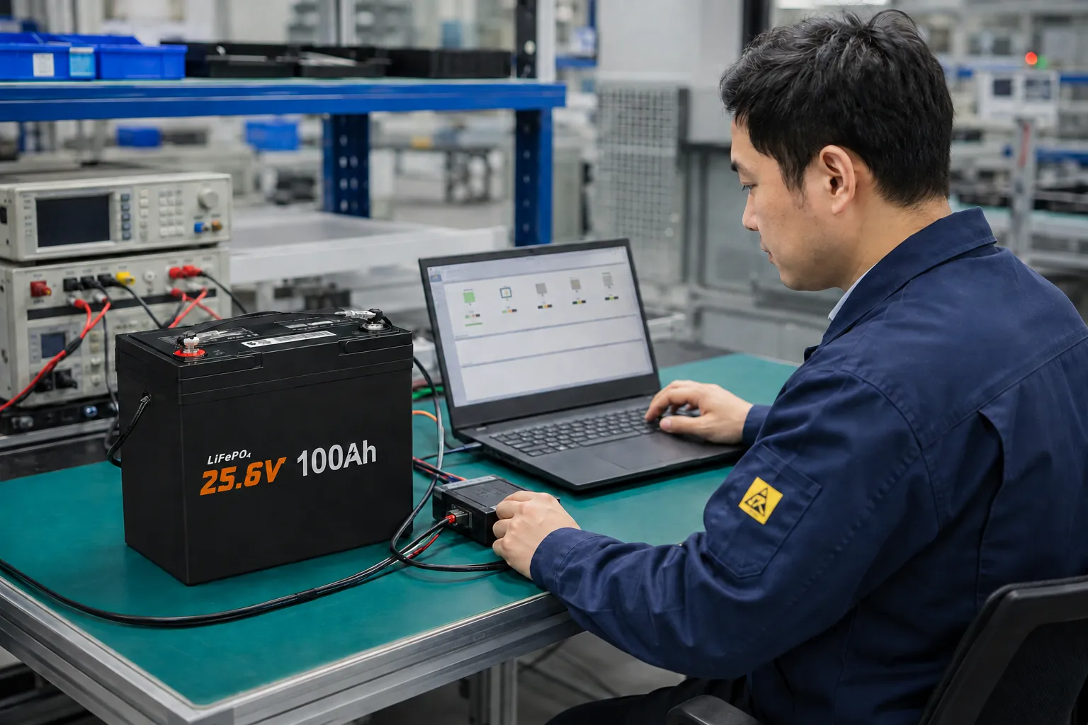
Selected configurations can support CAN or RS485 communication for battery status, current limits, state-of-charge reporting, and fault information. Protocol compatibility must be reviewed for the AGV or AMR controller and charging system, including the interface, baud rate, identifiers or device address, message definitions, connector, and pinout.
CAN and RS485 are not universal plug-and-play interfaces. The connected controller and charging equipment must be identified before sample development.
View LiFePO4 Battery Technical Support →
Mechanical integration should confirm the compartment opening, maximum battery dimensions, mounting points, permitted weight, terminal positions, connector access, cable bend radius, service clearance, and restraint method. Vibration, impact, temperature, dust, moisture, and the operating environment should be included in the engineering review.
For qualified OEM projects, enclosure dimensions, mounting details, connector selection, and wiring-harness layout can be evaluated as engineering options. These capabilities do not indicate that the vehicle shown on this page uses a completed custom configuration.
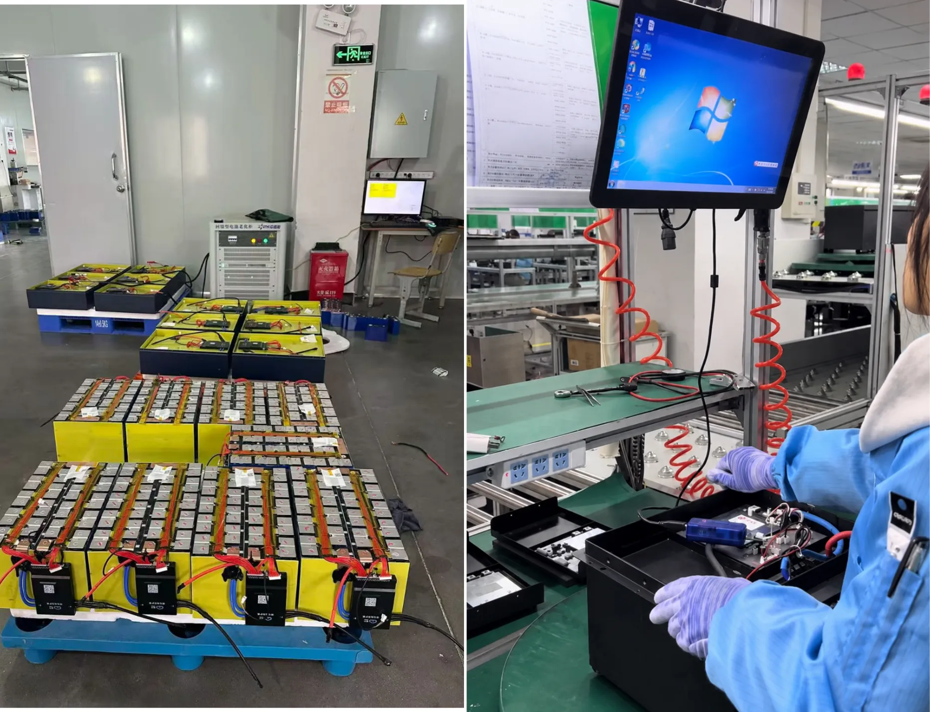
AGV manufacturers, AMR manufacturers, industrial automation companies, and system integrators can submit electrical, mechanical, charging, and communication requirements for review. Available OEM support can include battery specification review, BMS configuration, enclosure and connector development, sample evaluation, and controlled production.
Vehicle-level approval requires testing the selected sample with the actual equipment. The review may include measured average and startup current, peak duration, charging behavior, protocol communication, connector and cable temperature, mounting, vibration, and operating time. These are recommended validation steps, not claims that testing has already been completed for the vehicle shown.
View OEM & ODM Battery Services →
Use measured average current, required runtime, peak loads, charging intervals, reserve capacity, temperature, and available installation space. Nominal voltage and capacity alone are not sufficient.
Selected BMS configurations can support CAN or RS485. The protocol, controller, charger, firmware, cable, and pinout must be confirmed for the complete AGV battery system.
It may be retained only when its voltage, current, charging profile, contacts, communication logic, and safety controls match the approved battery configuration.
For an AGV LiFePO4 battery technical review, provide the system voltage, required operating hours, measured average and peak current, peak duration, controller model, charging strategy, installation dimensions, connector requirements, operating environment, and any CAN or RS485 protocol.